Size Steam or Gas Motive for Exhausting Gases
Using the Eductor Models SG and HG
 The Jacoby-Tarbox eductor eductor models SG and HG are general purpose eductors used to pump gas with a gas as the motive stream. They can be used to pull both liquid and gas suction loads. In this case, we will deal with gas suction stream applications. The model SG is generally used with higher pressure motive flows in the ranges of 60 to 120 PSIG. It is possible to use lower pressures with these units if the outlet pressures are strictly controlled. The model HG is designed to be operated with motive pressures of 20 through 80 PSIG. Because of the increased motive flow rate in this unit, it generally will discharge against higher pressures. In general, the SG will pull a deeper vacuum on the suction connection than the model HG. If it is possible to meet the discharge conditions with the model SG, this unit is generally more efficient. Both SG and HG models can be used to evacuate, exhaust, or prime a given area.
If the suction gas is not air at 70° F convert the suction gas to Dry Air Equivalent. If the suction units are not in Lb/Hr, refer to the back cover to convert from other units to Lb/Hr. If your units are not found here, go to a conversion table in a book of chemical standards.
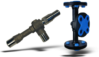
Eductors Specifications
There are three connections common to all venturi eductors.
Eductor MOTIVE Connection: This connection is where the power for the eductor is generated, by increasing the velocity of the motive fluid. The Jacoby-Tarbox eductor nozzle in this section takes advantage of the physical properties of the motive fluid. Eductors with liquid motives use a converging nozzle as liquids are not generally compressible. Eductors with gas motives utilize converging-diverging nozzles to achieve maximum benefit from the compressibility of the gas. All Jacoby-Tarbox eductor nozzles for eductors have smooth flow paths. Flow paths with sudden steps or roughness on these high velocity surfaces cause jet pumps to operate less efficiently.
SUCTION Connection: This connection of the eductor is where the pumping action of the eductor takes place. The motive fluid passes through the suction chamber, entraining the suction fluid as it passes. The friction between the fluids causes the chamber to be evacuated. This allows pressure in the suction vessel to push additional fluid into the suction connection of the jet pump. The high velocity of the motive stream in this section of the eductor directs the combined fluids toward the outlet section of the eductor.
Discharge Connection: As the motive fluid entrains the suction fluid, part of the kinetic energy of the motive fluid is imparted to the suction fluid. This allows the resulting mixture to discharge at an intermediate pressure. The percentage of the motive pressure that can be recovered is dependent upon the ratio of motive flow to suction flow and the amount of suction pressure pulled on the suction port. The mixture then passes through the diverging taper that converts the kinetic energy back to pressure. The combined fluid then leaves the outlet.
Instructions on Sizing Steam or Gas Motive Eductors for Exhausting Gases
Exhausting is a continuous operation of removing gases at a constant suction pressure. The units are sized based on a desired flow rate of gas through the eductor.
Step 1 Before beginning to do the actual sizing, convert all pressure and flow to the units used in the sizing table. (If sizing is done regularly with other units, request a special sizing table.
Step 2 First find the value that is equal to or greater than your system back pressure in the Outlet Pressure (Po) column. After locating the correct value on the sizing table, use this section of the table to size the unit.
Step 3 Locate the pressure that is equal to or higher than your desired suction pressure (Ps) for the outlet pressure found in Step 2. If the pressure is between two values on the sizing table, you can interpolate between them. If you don't wish to interpolate, the higher pressure will give a conservative estimate.
Step 4 In the row for suction pressure (Ps), locate the column where the motive pressure (Pm) is equal to your motive pressure in the flowing condition. If the pressure is between two levels on the sizing table, you can interpolate between the values. If you don't wish to interpolate, the lower pressure will give a conservative estimate.
Step 5 Divide your desired flow (Qs) rate by the flow rate of each model. This will give you a desired Sizing Factor (S.F.) for each model. Pick a unit with a S.E that is equal to or larger than the one calculated above.
Generally, the model with a larger suction capacity will be the more efficient unit. To calculate the actual gas flow, multiply the S.F. of the selected model by the suction flow (Qs) of the model in the table.
Step 6 Calculate the amount of water required to operate the eductor by multiplying the GPM in the Motive Flow (Qm) row by the S.F. of the unit selected.
Note 1: In many cases, the capacity of the MLE and ML units are close. Both should be sized to find the proper unit for the application.
Note 2: When using liquids to pump gases, the eductor acts as a volume displacing device. Therefore, the weight of the gas has only minimal effect on the performance of the eductor.
Example:
Desired Suction Flow, Qs.......... 5 Lb/Hr air
Desired Suction Pressure,Ps.......... 5 In Hg Vac
Motive Water Pressure, Pm.......... 40 PSIG
Outlet Pressure, Po.......... 11 Ft Head
Step 1 Convert the figures from given units to units used in the performance tables.
5 Lb/Hr x 13.35 Ft3/Lb/60 Minutes = 1.1 SCFM Air
5 In Hg Vac = 29.92 In Hg Abs
5 In Hg = 24.92 In Hg Absolute 40 PSIG is available
11Ft Head/2.31(Ft/PSIG)=4.8 PSIG
Step 2 Look down the Outlet Pressure (Po) column until the row is reached has 5 PSIG outlet pressure.
Step 3 Locate the suction pressure (Ps) that is equal to the desired suction pressure for the chosen outlet pressure. In this case, go to the section with a suction pressure of 25 In Hg Abs.
Step 4 Find the column in the 25 In Hg row that has a motive pressure (Pm) of 40 PSIG.
Step 5 Divide the suction flow desired by the Tabulated Suction Flow of each of the units to determine the desired S.F.
1.1 SCFM Desired/1.8 ML Tabulated Suction Flow = .65 Desired S.F.
1.1 SCFM Desired/3.7 MLE tabulated flow = .30 Desired S.F.
From the S.E's above, it appears that the MLE will be more efficient. The 1" unit has a S.F. of .34. When we multiply the S.F. by the suction flow for the 1-1/2" unit, we find an actual suction flow of:
.34 x 3.7 = 1.3 SCFM Actual Suction Flow
Step 6 The water needed to operate the MLE 1" will be 24.2 GPM x .34 S.F. = 8.2 GPM.